Check this out


Autocad Tutorials, Autocad 3D, Free Autocad Blocks

Autocad Tutorials, Autocad 3D, Free Autocad Blocks

Editing Dimensions and Other Objects Together.....

Editing Dimensions and Other Objects Together
It’s helpful to be able to edit a dimension directly by using its grips. But the key feature of AutoCAD’s dimensions is their ability to automatically adjust themselves to changes in the drawing.
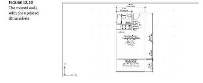
To see how this works, try moving the living room closer to the bathroom wall. You can move
a group of lines and vertices by using the Stretch command and the Crossing option:
1. Click the Stretch tool in the Modify toolbar, or type S↵ and then C↵. You’ll see the
following prompts:
At the Select objects to stretch by crossing-window or crossing-polygon...
Select objects: C
Specify first corner:
2. Pick a crossing window, as illustrated in Figure 12.9, and then press ↵ to confirm your
selection.


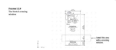
3. At the Specify base point or Displacement : prompt, pick any point
on the screen.
4. At the Specify second point or : prompt, enter
@2´<90↵ to move the wall 2´ in a 90° direction. The wall moves, and the dimension text changes to reflect the new dimensions, as shown in Figure 12.10.


5. After viewing the result of using the Stretch tool, click the Undo button in the toolbar or type U↵ to change the drawing back to its previous state. You can also use the Mirror, Rotate, and Stretch commands with dimensions. The polar arrays also work, and you can use Extend and Trim with linear dimensions. When you’re editing dimensioned objects, be sure to select the dimension associated with the object being edited. As you select objects, using the Crossing Window (C) or Crossing Polygon (CP) selection option helps you include the dimensions. For more on these selection options, see Chapter 2. TIP If a hatch pattern or solid fill completely covers a dimension, you can use the Draworder command to have AutoCAD draw the dimension over the hatch or solid fill. See Chapters 7, 14, and 18 for more on various uses of the Draworder command. Modifying the Dimension Style Settings by Using Override
In the “Moving Fixed Dimension Text” section, you used the Properties palette to facilitate the moving of the dimension text. You can also choose Dimension  Override (Dimoverride command) to accomplish the same thing. The Override option enables you to change an individual dimension’s style settings.
Here’s an example that shows how you can use the Override option in place of the Properties
palette in the first exercise of the “Moving Fixed Dimension Text” section:
1. Press the Esc key twice to make sure you aren’t in the middle of a command. Then, choose Dimension  Override from the drop-down menu.
2. At the next prompt Enter dimension variable name to override or [Clear overrides]: type Dimfit↵.
3. At the Enter new value for dimension variable <3>: prompt, enter 4↵. This has the same
effect as selecting Move Text, Add Leader from the Fit option of the Properties palette.
4. The Enter dimension variable name to override: prompt appears again, enabling you to
enter another dimension variable. Press ↵ to move to the next step.
5. At the Select objects: prompt, select the dimension you want to change. You can select a group
of dimensions if you want to change several dimensions at once. Press ↵ when you’ve finished with your selection. The dimension settings change for the selected dimensions.
As you can see from this example, the Dimoverride command requires that you know exactly which dimension variable to edit in order to make the desired modification. In this case, setting the Dimfit variable to 4 lets you move the dimension text independently of the dimension line. If you find the Dimoverride command useful, consult Appendix C to determine which system variable corresponds to the Dimension Style dialog box settings.